One of the problem with running servers in a home environment is the lack of 100% reliable electricity. I’ve noticed that since moving house nearly 2 years ago, going from underground to above ground power, has resulted in a significant reduction in grid reliability. There have been frequent outages due to replacing power poles, road accidents that have destroyed poles and other maintenance that just wasn’t an issue in our old place. To cut a long story short, this means I have a renewed interest in monitoring my uninterruptible power supplies (UPS) for outages so I can respond. Ordinarily I would use email for this, however my alerts go to a separate folder and I which I only check periodically and when I’m in the office or out on the weekend, I need to know instantly if there is an issue.
This is where push notifications come in handy. Nextcloud has a function to allow administrators to send notifications so I needed to write a script that hooks into the API and sends the message. The steps are simple enough:
- Create a service account for sending API notifications in Nextcloud
- Create an API key for the above
- Create the script to be executed by the network UPS tool monitoring service that will send an email and call another script (below)
- Create a script that will send the push notification.
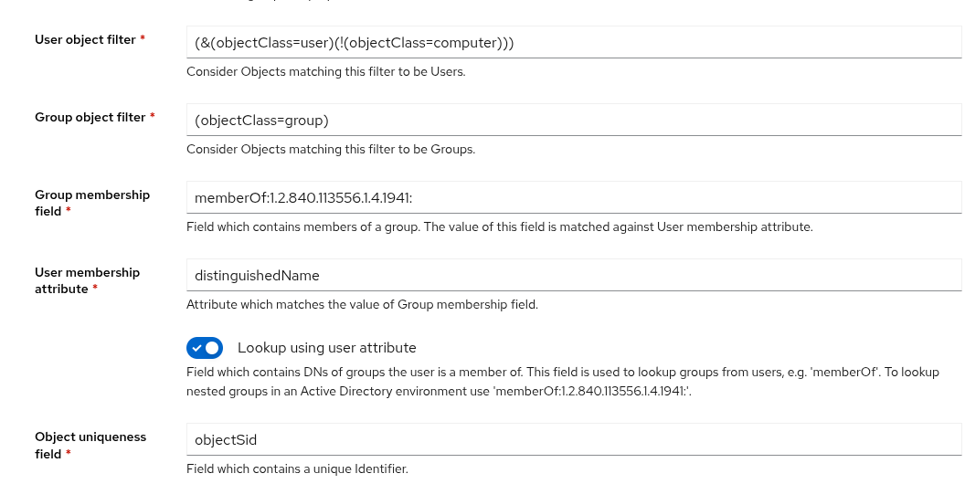
Starting with the service account, however you would normally do it, depends on your circumstances. In mine, I created an service account in AD, then in Nextcloud granted the minimum required permissions to be able to send notifications to that account. If you’re doing it this way, you’ll need the ObjectGUID from AD later. If necessary create an app password in nextcloud for the service account.
Edit the file /etc/nut/upsmon.conf and add the following to the NOTIFTYCMD section:
NOTIFYCMD /usr/local/bin/nut-email.sh
Create the script below in the correct location (/usr/local/bin/nut-email.sh) and make it executable and owned by root. This script will send an email and then run another script to send the push notification.
#!/bin/bash
# /usr/local/bin/nut-email.sh

TO="youremail@yourdomain.tld"
SUBJECT="UPS Alert: $UPSNAME $NOTIFYTYPE"
BODY="Event: $NOTIFYTYPE occurred on $UPSNAME at $(date)."

echo "$BODY" | mail -s "$SUBJECT" "$TO"

# execute push notifcation
export SUBJECT
/usr/local/bin/nut-push.py
Create the script for interacting with nextcloud’s notification app in the location /usr/local/bin/nut-push.py. Ensure it is owned by root and executable.
#!/usr/bin/env python3
import requests, os
from requests.auth import HTTPBasicAuth
# Your Nextcloud configuration
NEXTCLOUD_URL = 'https://your.nextcloud.url'
USERNAME = 'service_account@yourdomain.tld'
PASSWORD = 'account_password'
# Notification content
MESSAGE = ' '+os.getenv('SUBJECT')
# MESSAGE = ' UPS warning: Power failure detected. System may shut down soon.'
# API endpoint
url = f'{NEXTCLOUD_URL}/ocs/v2.php/apps/notifications/api/v2/admin_notifications/<ObjectGUID>'
# Headers required by Nextcloud OCS API
headers = {
'OCS-APIREQUEST': 'true',
#'Content-Type': 'application/x-www-form-urlencoded'
}
# Payload
payload = {
'shortMessage': MESSAGE
}
# Make the request
response = requests.post(url, headers=headers, data=payload, auth=HTTPBasicAuth(USERNAME, PASSWORD))
# Check result
if response.status_code == 200:
print('Notification sent successfully!')
else:
print(f'Failed to send notification: {response.status_code}, {response.text}')
And thats it! You should be able to test this by executing the script above.