Vodafone NBN (FTTP) IPv6 Prefix Delegation on a Ubiquiti EdgeRouter Lite

Background

I’ve always been intimidated by IPv6, the addresses were long and confusing, and not fully understanding the technology made me nervous to integrate it into my systems. How did it work? Would enabling it expose everything in my LAN to the internet? Would I find myself under attack without realising it?

Well, the good news is that smarter people have already thought about the problems above (and more) and engineered an addressing system with built-in security and automatic configuration (SLAAC). So if you use a firewall on your router, IPv6 will give you the benefits of having externally accessible IP addresses on your LAN that can be routed, if you allow it.

I found a lot of misinformation and confusion around IPv6 online. So if you’re looking for general information on IPv6 review the videos below, I also found the instructions here: https://medium.com/@nurblieh/ipv6-on-the-edgerouter-lite-c95e3cc8d49d invaluable.

Finally, I was able to guess at the correct settings to use on Vodafone NBN to obtain IPv6 addresses. I called Vodafone’s support number – email, weirdly, wasn’t an option – unfortunately their support wasn’t great, and all I was able to find was that they do offer IPv6, but not technical advice. Thankfully their IPv6 technology implementation is standard to the point of being boring and I guessed at the right settings, eventually getting it right.

Configuration

To get IPv6 prefix delegation working on the edgerouter with Vodafone FTTP NBN a few steps need to be taken:

  1. Setup the firewalls WAN6_In and WAN6_LOCAL on the EdgeRouter to allow IPv6 traffic and assign it to the internet interface.
  2. Enable dhcpv6-pd on the internet Ethernet port, request a /56 from Vodafone.
  3. Delegate /64 subdomains to each interface on your network. If I understand it correctly, there should be 255 available networks to assign.
  4. I personally disable DNS name servers being advertised to

Generally I use the config tree to do configuration, however to save time, I’ve included below the relevant settings to enable IPv6 taken from the config file. If I’ve missed something please let me know in the comments.

The below settings contain the firewall settings for an IPv6 connection. I’ve removed IP addresses, but left the configuration to show to poke holes in the firewall to allow services through directly to servers. As it has been mentioned elsewhere on the internet, allowing ICMPv6 through is critical for IPv6 to function correctly.

firewall {
     ...
     ipv6-name WAN6_IN {
         default-action drop
         rule 10 {
             action accept
             description "allow established"
             protocol all
             state {
                 established enable
                 related enable
             }
         }
         rule 20 {
             action drop
             description "drop invalid packets"
             protocol all
             state {
                 invalid enable
             }
         }
         rule 30 {
             action accept
             description "allow ICMPv6"
             protocol icmpv6
         }
         rule 40 {
             action accept
             description "allow traffic for www"
             destination {
                 address xxx
             }
             protocol tcp
         }
         rule 41 {
             action accept
             description "Allow SSH (v6) to Atlas"
             destination {
                 address xxx
                 port 22
             }
             protocol tcp
         }
         rule 42 {
             action accept
             description "Allow Ipv6 to Plex"
             destination {
                 address xxx
                 port 32400
             }
             protocol tcp
         }
     }
     ipv6-name WAN6_LOCAL {
         default-action drop
         rule 10 {
             action accept
             description "allow established"
             protocol all
             state {
                 established enable
                 related enable
             }
         }
         rule 20 {
             action drop
             description "drop invalid packets"
             protocol all
             state {
                 invalid enable
             }
         }
         rule 30 {
             action accept
             description "allow ICMPv6"
             protocol icmpv6
         }
         rule 40 {
             action accept
             description "allow DHCPv6 client/server"
             destination {
                 port 546
             }
             protocol udp
             source {
                 port 547
             }
         }
     }

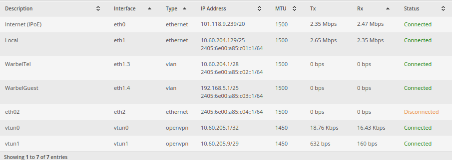
The below section contains the details on how to configure an interface for dhcpv6-pd. You may notice that I have multiple interfaces that I have advertised IPv6 to. It’s important to realise the function of the prefix-id and host address fields. The prefix-id is, apparently, a 2 digit hexadecimal number from 00 to FF representing 0-255. It indicates which /64 subnet to assign to the interface. The host address is the address that the router will assign itself on that subnet. I’ve disabled dns on my interfaces, as I would prefer my systems to use my internal DNS for all requests and my internal DNS servers are configured to resolve A and AAAA records.

interfaces {
     ethernet eth0 {
         address dhcp
         description "Internet (IPoE)"
         dhcpv6-pd {
             pd 0 {
                 interface eth1 {
                     host-address ::1
                     no-dns
                     prefix-id :1
                     service slaac
                 }
                 interface eth1.3 {
                     host-address ::1
                     no-dns
                     prefix-id :2
                     service slaac
                 }
                 interface eth1.4 {
                     host-address ::1
                     no-dns
                     prefix-id :3
                     service slaac
                 }
                 interface eth2 {
                     host-address ::1
                     no-dns
                     prefix-id :4
                     service slaac
                 }
                 prefix-length /56
             }
             rapid-commit enable
         }
         duplex auto
         firewall {
             in {
                 ipv6-name WAN6_IN
                 name WAN_IN
             }
             local {
                 ipv6-name WAN6_LOCAL
                 name WAN_LOCAL
             }
         }
         ip {
         }
         ipv6 {
             address {
                 autoconf
             }
             dup-addr-detect-transmits 1
         }
         mtu 1500
         speed auto

Further Notes

I found that implementing IPv6 wasn’t perfect. As I kept playing with the settings, my networked hosts would, using SLAAC, get another IPv6 address without removing the old one and instead just mark them as stale. The easy fix was to manually remove the addresses, but it was tedious. I also had to modify my web server’s configs to properly respond to IPv6 requests. I did that by adding [::]:443 to the virtual host directive eg: <VirtualHost blog.warbel.net:443 [::]:443>

Tools

https://www.vultr.com/resources/subnet-calculator-ipv6/ – The Vultr IPv6 subnet calculator is very handy. As is this calculator: http://www.gestioip.net/cgi-bin/subnet_calculator.cgi
IPv6 up and running

Configuring a Raspberry Pi 2 with a Huwei K4203 USB 3G Modem

Background/Overview:

My Wife and I like to travel overseas and we both have multiple devices when we travel. Over the years we’ve tried different solutions. From buying ‘travel’ sims before we leave that end up costing a fortune, to just enabling roaming on our phones and again, paying heavily for international data roaming.

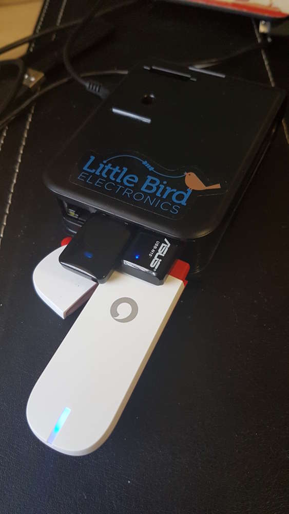
After doing a little research on the best deal and wanting a flexible option, I bought a 3G dongle from Vodafone. A Huawei K4204 to be precise. My goal is to create a Raspberry Pi that will connect to the hotel WiFi when available and will have it’s own AP running on a different channel so that our devices only have to remember one Access Point.  This will circumvent certain hotels that only allow you to connect a single device to their network. It will also mean that if we have a Google Chromecast I only have to program a single network into it and use it when we travel. The Raspberry Pi will have a 3G data connection when no Hotel WiFi is available or we’re out and about. When we arrive at our destination (the UK) we will buy a local sim with local (read: cheap) data.

The below steps are how I achieved the above:

Part 1: Initial Setup

Install Raspbian in any way you prefer. I’ve installed the lite version that has no gui.

Use dd to write to the disk, in my case the microSD card was at /dev/sdd:

sudo dd if=2017-04-10-raspbian-jessie-lite.img of=/dev/sdd bs=2M

log in as pi, password: raspberry

add a new user and add the user to the sudo group so you can edit system files:

sudo adduser wargus;sudo usermod -a -G sudo USERNAME

log in as your new user, remove pi

sudo deluser pi

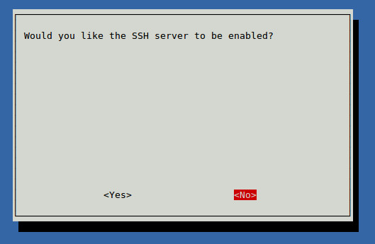
enable ssh by default using raspi-config

sudo raspi-config

Under Interfacing Options, 2, Enable SSH:

Check the IP address of the raspberry pi, it should be set to dhcp automatically.

ifconfig 
eth0 Link encap:Ethernet HWaddr 00:00:00:00:00:00 
 inet addr:10.60.204.182 Bcast:10.60.204.255 Mask:255.255.255.128
 UP BROADCAST RUNNING MULTICAST MTU:1500 Metric:1
 RX packets:7511 errors:0 dropped:12 overruns:0 frame:0
 TX packets:2759 errors:0 dropped:0 overruns:0 carrier:0
 collisions:0 txqueuelen:1000 
 RX bytes:669438 (653.7 KiB) TX bytes:604742 (590.5 KiB)

At this point you can disconnect the terminal and use SSH to connect to your raspberry device.

Configuring usb_modeswitch

I used this site as a reference. It was mostly right for me, although I did have to do a lot troubleshooting before I had it completely right.

cd /tmp
tar -xzvf /usr/share/usb_modeswitch/configPack.tar.gz 19d2\:1f1c

Will create a new file in the tmp directory it will need to be further edited to look like this:

# Vodafone / Huawei K4203
DefaultVendor=0x12d1
DefaultProduct=0x1f1c
TargetVendor=0x12d1
TargetProductList="157a,1590"
HuaweiNewMode=1

Copy or move that file to /etc/usb_modeswitch.d/

At this point with a fresh install, you should be able to plug in the dongle. Switch the usb mode by running :

sudo usb_modeswitch -c /etc/usb_modeswitch.d/12d1\:1f1c

Check the switch by using lsusb, as the output suggests.

lsusb
Bus 001 Device 007: ID 12d1:1590 Huawei Technologies Co., Ltd. 
Bus 001 Device 004: ID 0bda:8178 Realtek Semiconductor Corp. RTL8192CU 802.11n WLAN Adapter
Bus 001 Device 003: ID 0424:ec00 Standard Microsystems Corp. SMSC9512/9514 Fast Ethernet Adapter
Bus 001 Device 002: ID 0424:9514 Standard Microsystems Corp. 
Bus 001 Device 001: ID 1d6b:0002 Linux Foundation 2.0 root hub

In my setup, the dongle flashed green, flashed blue, then goes solid blue. A quick check of ifconfig at this point shows that the dongle presents itself as a new Ethernet adaptor:

ifconfig 
...
eth1 Link encap:Ethernet HWaddr 00:00:00:00:00:00 
inet addr:192.168.9.100 Bcast:192.168.9.255 Mask:255.255.255.0
UP BROADCAST RUNNING MULTICAST MTU:1500 Metric:1
RX packets:55 errors:0 dropped:0 overruns:0 frame:0
TX packets:38 errors:0 dropped:0 overruns:0 carrier:0
collisions:0 txqueuelen:1000 
RX bytes:16310 (15.9 KiB) TX bytes:7400 (7.2 KiB)

The dongle automagically configures itself and connects to the internet. 🙂 Remember that at this point to connect to the internet will require you to manually set the dongle to the correct mode.

Test the connection by pinging over the interface:

ping www.google.com -I eth1
PING www.google.com (203.219.197.210) from 192.168.9.100 eth1: 56(84) bytes of data.
64 bytes from cache.google.com (203.219.197.210): icmp_seq=1 ttl=55 time=2254 ms
64 bytes from cache.google.com (203.219.197.210): icmp_seq=2 ttl=55 time=1248 ms
64 bytes from cache.google.com (203.219.197.210): icmp_seq=3 ttl=55 time=248 ms

ping www.google.com -I eth0
PING www.google.com (203.219.197.245) from 10.60.204.182 eth0: 56(84) bytes of data.
64 bytes from cache.google.com (203.219.197.245): icmp_seq=1 ttl=60 time=1.85 ms
64 bytes from cache.google.com (203.219.197.245): icmp_seq=2 ttl=60 time=1.50 ms
64 bytes from cache.google.com (203.219.197.245): icmp_seq=3 ttl=60 time=2.33 ms

Part 2: Routing Configuration

At this point, we have a very smart little independently internet connected Raspberry Pi. What we want to do next is a little more complicated. We’re going to configure it to be an access point that will hand out IP addresses and handle NAT. unfortunately it won’t be smart enough to switch between wifi and 3G automatically however you can connect and do that yourself. 😉

Linux by default does not know that it is a router. We need to enable that functionality and, while we’re there, disable IPv6 (which is something of a security concern).

Edit /etc/sysctl.conf with your favourite editor and uncomment the line:

net.ipv4.ip_forward=1

Add the following lines:

net.ipv6.conf.all.disable_ipv6=1
net.ipv6.conf.default.disable_ipv6=1

Then run the following command to make the changes apply:

sudo sysctl -p

Install hostapd and configure your wifi dongle to be an access point:

sudo apt-get install hostapd -y

Edit the primary wifi dongle to be an access point by editing /etc/hostapd.conf

channel=3
country_code=AU
hw_mode=g
interface=wlan0
ssid=SSIDNAME
wpa=2
wpa_key_mgmt= WPA-PSK WPA-EAP WPA-PSK-SHA256 WPA-EAP-SHA256
wpa_passphrase=PASSPHRASE

You will need to edit the above to suit. Be sure to check what channels are being used and pick one that does not have too much interference.

Now edit the /etc/network/interfaces file and change wlan0’s settings:

auto wlan0
allow-hotplug wlan0
iface wlan0 inet static
hostapd /etc/hostapd/hostapd.conf
address 10.60.205.129
netmask 255.255.255.128
broadcast 10.60.205.255
dns-nameservers 8.8.8.8 8.8.4.4

To save heartache later, edit the default settings for eth0 to:

iface eth0 inet dhcp

To explain the above: I’ve gone with a small 10.60.205.128/25 IP range and I’ve set google’s name servers to be my defaults. It is necessary to change eth0’s settings as it will fail to come up when we change some service settings below.

Finally, setup a dhcp server. I tend to prefer a more robust dhcp server:

sudo apt-get install isc-dhcp-server

Configure it to only operate on the wlan0 interface by editing /etc/default/isc-dhcp-server and changing the line INTERFACES=”” to

INTERFACES="wlan0"

Edit the configuration file for the dhcp server in /etc/dhcp/dhcpd.conf Change various options at the top to match your own configuration, the important points to recognise are:

# option definitions common to all supported networks...
option domain-name "yourdomain.local";
option domain-name-servers 8.8.8.8, 8.8.4.4;

subnet 10.60.205.128 netmask 255.255.255.128 {
range 10.60.205.150 10.60.205.190;
option routers 10.60.205.129;
option broadcast-address 10.60.205.255;
}

This will create a range of IP addresses to assign to devices as needed from 150 to 190.  We still won’t have routing yet, but we’re nearly there! Enable the dhcp service:

sudo systemctl enable isc-dhcp-server.service

Start the dhcp server:

sudo service isc-dhcp-server start

It should be safe to start the service now, and test  everything be restarting it. if you connect a device to the network it will be able to get an IP address, it just won’t have any internet access.

If you have another wifi dongle, as I do, it can also be configured to be a client to another wireless network. This is handy if your hotel only allows one device to be connected to their wifi and you have many devices. Connect the Raspberry Pi to their network and have it do NAT to your devices.

The Configuration at home may be different to the hotel, which is why I’ve included the note in the configuration below to remind me where to look for information. Remember, if you need to find more information you can always use the 3G dongle to get access to the internet 🙂

#Configure the roaming interface
#Use 'sudo iwlist scan' to find an AP to join
auto wlan1
allow-hotplug wlan1
iface wlan1 inet dhcp
wpa-ssid SSID_OF_NETWORK
wpa-psk PASSWORD

The Final Steps: Routing and Firewalling.

At this point we can write a simple script called firewall to allow routing. It can be placed in /etc/init.d/.

#!/bin/bash

# Iptables Location
IPTABLES="/sbin/iptables"
#Load Modules#

##########################################################
#
# Don't Touch anything below this line!
#

case "$1" in start)

echo "Starting Firewall Services"
echo "Firewall: Configuring firewall rules using iptables"

#BEGIN FIREWALL ROUTING HERE

#We want the 3G router to start when the firewall does. So we use usb switch here:
usb_modeswitch -c /etc/usb_modeswitch.d/12d1\:1f1c

#Flush Routing Table
$IPTABLES -F
$IPTABLES -t nat -F
$IPTABLES -t mangle -F
$IPTABLES -t mangle -X
$IPTABLES -X

# default policy
 $IPTABLES -P INPUT ACCEPT
 $IPTABLES -P FORWARD ACCEPT
 $IPTABLES -P OUTPUT ACCEPT

# allow established,related
 $IPTABLES -A INPUT -m state --state ESTABLISHED,RELATED -j ACCEPT
 $IPTABLES -A FORWARD -m state --state ESTABLISHED,RELATED -j ACCEPT

# Masquerade over both routes
 $IPTABLES -t nat -A POSTROUTING -o eth1 -j MASQUERADE
 $IPTABLES -t nat -A POSTROUTING -o wlan1 -j MASQUERADE
#END FIREWALL ROUTING HERE

touch /var/lock/firewall
;;
status)
 if [ -f /var/lock/firewall ]; then
 echo "Firewall started and configured"
 else
 echo "Firewall stopped"
 fi
 exit 0
 ;;

restart|reload)
 $0 stop
 $0 start
 ;;

stop)
 echo "Shutting down Firewall services"

#Flush Routing Table
$IPTABLES -F
$IPTABLES -t nat -F
$IPTABLES -t mangle -F
$IPTABLES -t mangle -X
$IPTABLES -X

# default policy
 $IPTABLES -P INPUT ACCEPT
 $IPTABLES -P FORWARD ACCEPT
 $IPTABLES -P OUTPUT ACCEPT

 rm -f /var/lock/firewall
 echo
 ;;
 *)
 echo "Usage: /etc/init.d/firewall {start|stop|status|restart|reload}"
 exit 1
esac
exit 0

I’ve noticed that by default the router will route traffic over the wlan1 before eth1, even if eth1 exists and has internet access. This is useful as it means that we can have a single firewall/routing script for both connections. It will fail-over to the 3G dongle when no appropriate WiFi AP can be found.

Install the script with:

sudo update-rc.d firewall defaults

At this point I was able to power down the Raspberry Pi. On coming back online the two dongles didn’t work, but the 3G dongle did. As hotplug is enabled on those two wifi dongles, removing and re-inserting them got them working again. I was then able to connect to the internet (and the Pi) over WiFi. Removing the dongle connecting to my home network immediately failed over to the 3G dongle.

Which brings us to the end!