Building an Arduino Weather Station with ELK Stack

Having recently been introduced to the Elastic, Logstash, Kibana (ELK) stack by a colleague and having wanted to build a home-brew weather station for some time, I decided to combine both projects. There was surprisingly little information available online about building an arduino weather station and although it had been done, everyone seems to have their own take, and hardware requirements. Two sites provided useful information for this project:

  1. The manufacturer’s wiki of the weather station components and;
  2. This blog entry, written by a staff member at Elastic.co.

As a side note, once I figured out how to use ELK Stack and setup my data types, I also integrated information from a Fronius Inverter too. The inverter has a well documented API that outputs its data in JSON format. I used logstash to periodically pull the data from the inverter and output it into Elasticsearch. My Arduino is setup in a similar way to the Inverter: It hosts a simple website that only displays the current weather data in a JSON format.

Things you will need:

  • An ELK stack. Elastic co provide significant documentation on setting up Elastic stack, so for the sake of simplicity I wont be covering this here.
  • A weather station with anemometer from dfrobot or a supplier, I bought my equipment from littlebird electronics. 
  • An Arduino with an Ethernet shield, or an Freetronics Etherten.
  • A passive PoE adaptor to supply power to your Arduino.
  • The latest version of the Arduino IDE, and the Time library added into your Arduino environment. I prefer to do my coding in Microsoft Visual Studio Code which has plugin support for Arduino.
  • Cat6 cable, telephone cabling (with RJ11 headers), some M->F breadboard cabling, waterproofed project box, appropriate mast that can support the weather station if needed.
  • Access to my source code on Github.

Building and Programming the Hardware:

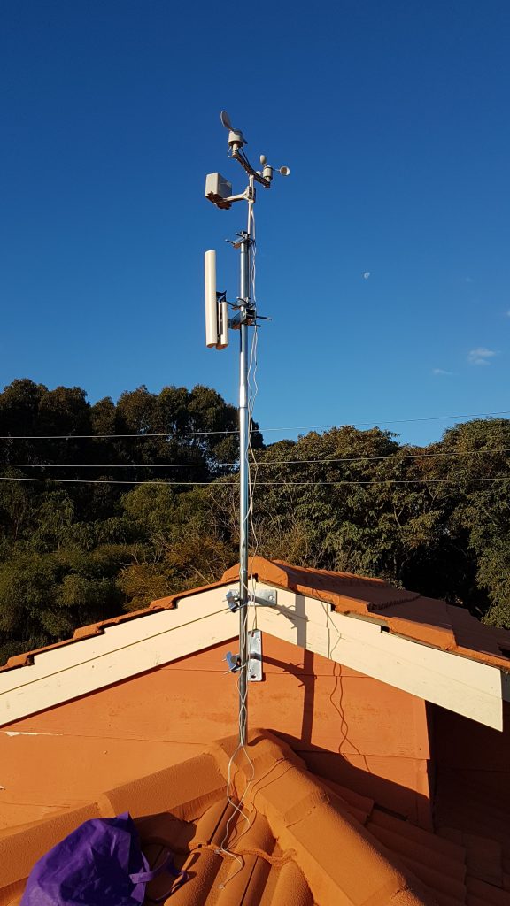
In my case, I opted to build a new, more stable mast, entirely separate from my TV antenna mast. Bunnings was able to provide the mast equipment I needed. As you may notice, I have also mounted a Ubiquiti Rocket M5 with a 120 degree antenna (nothing to do with this project!).

New Mast

Unfortunately the serial cables provided in the weather station kit were not long enough to do anything useful, so I had to buy two RJ11 joiners, RJ11 headers and cabling to extend the cabling to the eves where I mounted the electronics.

Roofing cabling

Project box mounted under the eves


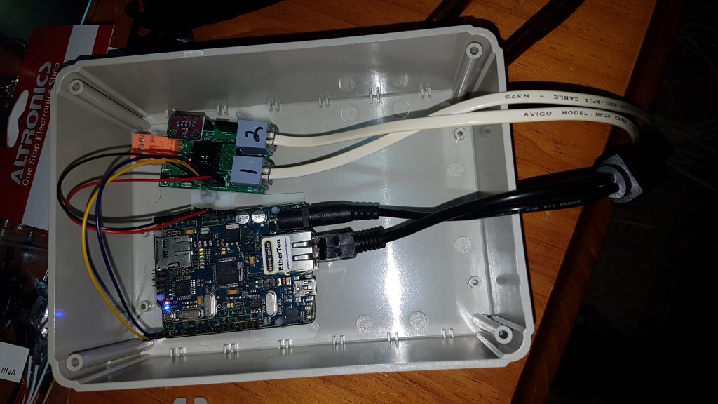
It ended up being quite a task running the cabling to the eves, but it was worth it in the end! As I wanted to mount the sensors outside, I opted to go with a power-over-ethernet (PoE) system which required a Cat6 cable and passive PoE injectors. The weather station sensors on the roof are connected to the weather station circuit board via the two RJ11 cables Pictured below:


The Arduino and sensors were mounted DIY fashion inside a project box. I used a dremel to cut a hole in the plastic lid to feed the cabling through so that it would sit flush with the eves.

Programming:

Arduino:

In order to collect and output the data I had to recycle some code from the Arduino website, and some code from other places (credit in the code). My contribution was building in some error checking. The sensor unit, as it turned out, was not always accurate and would quite often return garbage data. In order to fix this I programmed the arduino to check the data twice and compare the results. Both results had to pass a sanity check: Here in Perth, WA it never gets below -5 or above 55, nor does the barometric pressure wildly fluctuate either. So, only report the data if the data was within range, and the values had to be reasonable close to each other. Strictly speaking this will not stop all bad data, but it seems to do a good enough job 99.99% of the time. See above for a link to my github project.

ELK Stack:

I’ve provided on github the pipeline configuration you will need in order to use logstash to connect to your arduino and pull the json data. If you don’t have an openweathermap account, it is possible to remove the appropriate section from the 01-http-weather.conf file. You will need to add the files to your /etc/logstash/conf.d directory and add the pipelines to logstash by modifying the pipelines.yml file.

The last step will be to use the code snippets in the mappings_script file.  From within the dev tools section of  Kibana, run the below PUT command. This will tell Elasticsearch about the data coming in and correctly map the data types:

PUT /weather/_mappings/doc
{
"properties": {
"coord": {"type": "geo_point"},
"coordlocal": {"type": "geo_point"},
"dt": {"type": "date"},
"localdt": {"type": "date"},
"sys.sunrise": {"type": "date"},
"sys.sunset": {"type": "date"},
"clouds.all": {"type": "float"},
"main.humidity": {"type": "float"},
"main.temp": {"type": "float"},
"main.pressure": {"type": "float"},
"rain.3hr": {"type": "float"},
"visibility": {"type": "float"},
"weather.humidity": {"type": "float"},
"weather.temp": {"type": "float"},
"weather.pressure": {"type": "float"},
"wind.deg": {"type": "float"},
"wind.speed": {"type": "float"},
"wind.localspeed": {"type": "float"},
"wind.localdeg": {"type": "float"},
"wind.localgust": {"type": "float"},
"localrain.1h": {"type": "float"},
"localrain.24h": {"type": "float"}
}
}

And that is it!

At this point, you should have a working weather station with log stash pulling the data and pushing it to elasticsearch. I haven’t detailed how to build the graphs or dashboards to display the data, but there is plenty of documentation available online. 

Sensor Inaccuracy/Future Improvements:

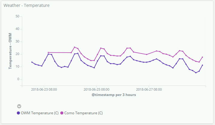
After mounting the sensors I had discovered that the heat generated from the electronics does interfere with the reading. The top line represents the temperature read from my weather station, and the bottom line is data from OpenWeatherMap.

The solution, when I have time later, will be to drill more holes in the project box to allow better air flow and partition the arduino away from the sensors to better isolate the heat that is generated.


Using Xnest or Putty/VcXsrv to Start a Full Remote Session

As useful as ssh and command-line (CLI) tools are when using a Linux/Ubuntu system remotely, sometimes it simply isn’t enough. And I dare say, sometimes it’s better to use a graphical tool to do something than it is to use the CLI alternative- parted/gparted: I’m looking at you!

Sometimes you may even want to use a full graphical desktop remotely (audible gasps!). This can be handy if you’re developing a desktop system on a remote server or virtual machine and want to experience the system the same way as the end user. I’ve found it useful when developing Linux code from a Windows desktop, and want to run a full development environment remotely. Setting up a remote session too, I’ve found, resolves some quirky display issues when using a proprietary program with a GUI remotely.

In this tutorial I’ll show you how to tunnel X11 through ssh to both a computer running Windows with Putty and VcXsrv and a Linux computer with Xnest. I will show you how to tunnel and entire desktop session or an individual program.

Before we begin, configure the remote server:

I’m assuming that port 22 is open on your remote server and you are capable of logging into the server with ssh.

Edit the file /etc/ssh/sshd_config (with sudo if necessary)

sudo vi /etc/ssh/sshd_config

And ensure that X11Forwarding yes is set and set AddressFamily inet:

X11Forwarding yes
...
AddressFamily inet

WARNING: Setting AddressFamily to inet will force ssh to only use ipv4 addresses. If you use IPv6, then this tutorial is not for you!

Next, install lxde – a lightweight desktop environment:

sudo apt install lxde lxdesession 

Generally, I prefer using Linux Mint with Cinnamon, but LXDE provides a nice environment that does not use a lot of network bandwidth. There are alternatives through, and I do suggest you look into them if you’re interested.

Finally, restart ssh, log out and log back into your server to make sure everything is working.

sudo service ssh restart;exit

Lets start with the easier option first: Linux:

Running a single program remotely:

At this point your remote server is already configured to allow ssh +X11 forwarding. if you log into your remote server and run a graphical program (assuming it is installed) the program will magically appear in front of you. Be aware that it will take over your terminal unless you push it to the background with ampersand (&), for instance:

user@RemoteServer$ gparted &

If you experience trouble at this point, it is worth connecting with ssh using the -vv -X flags to see the error messages.

Running an entire session remotely: 

On your Linux/Ubuntu/Mint Desktop, open a terminal and install xnest:

sudo apt install xnest

Xnest is both an X11 server and X11 client. There is a lot written about it, so again, google is your friend if you want more information. Once insalled, create a new script called remote_session.sh, make it executable and edit it:

touch remote_session.sh;chmod +x remote_session.sh;vi remote_session.sh

Add the following, modified to suit your personal circumstances:

#!/bin/bash

Xnest :3 -ac -geometry 1500x990 &
export DISPLAY=:3
ssh HOSTNAME_OF_REMOTE_SERVER lxsession

The bash script is very simple and is in three parts.
The first line calls Xnest, starting a new X11 server, fully windowed with the dimensions 1500×900, you will need to adjust this to your preferred resolution. Then export will tell all your graphical programs to use Xnest, rather than your original X11 server. This will only apply to programs run from your current terminal. Finally, the last command, ssh will connect remotely to your server and run lxsession, the lxde session manager. If it is all successful, you should have a new window appear with a full desktop session appearing in it. 

Run the script by typing at the terminal:

./remote_session.sh

Lxde Session running in Xnest

Your session may not have the nice background picture, which i set to Greenish_by_EstebanMitnick.jpg in /usr/share/backgrounds.

Once finished working in the remote session, simply close your programs like normal, and close the Xnest window.

Connecting From Windows:

The process is very similar to the above. I’ve assumed you’ve installed VcXsrv and are somewhat familiar with Putty.

Running a Single Program:

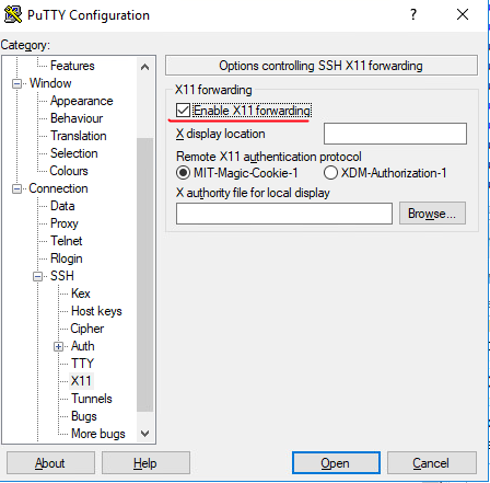
To run single program so that it integrates into your Windows environment, launch the VcXsrv program by double-clicking its icon on the desktop. Its icon will appear in your notifications area. Open putty, and ensure that Enable X11 forwarding is ticked in the putty options before connecting to your box:

Tick the box!

Once logged in, run your graphical program via putty, and it should appear magically in front of you! (This is my preferred way to access virt-manager from a windows computer).

Running an Entire Session:

The process to connect with putty is the same, except that instead of running a graphical program, say gparted, you start a session manager, lxsession, for instance.

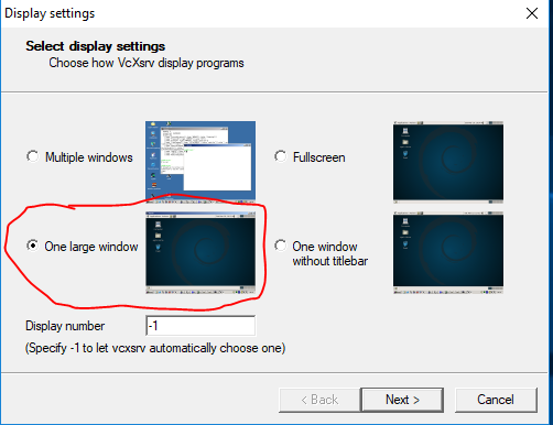
Additionally, you will need to use Xlaunch which will ask you to configure your X11 server.

Select the One Large Window option when prompted.

Most of the options that XLaunch presents can be clicked through without modification, just ensure you choose ‘One Large Window’.

Once you’ve run VcXsrv as outlined above, log in with putty and run your session manager: lxsession and boom! You should have an entire remote session running on your windows computer.

Remote Linux on Windows!

UWA Boat Club Event Photos – 2008

As per a recent request, the photos I took during 2008 of events attended by or organised by the University of Western Australia Boat Club (UWABC). Photos remain my property and cannot be reproduced without permission.

How to configure a Unifi Controller behind an Apache Reverse Proxy with LetsEncrypt

Background:

I had to do quite a bit of searching in order to get Unifi to work correctly behind an Apache reverse proxy. I found that many people had come up with their own solutions with various odd, to say the least, configuration options in Apache that were mostly unnecessary. It took a little more searching, but eventually I did find how to prevent the WSS error from appearing too.

Before Beginning:

I assume that you have:

  • Already configured Apache and Lets Encrypt previously.
  • DNS already configured correctly and you can easily add another sub-domain.
  • Already installed and configured Unifi Controller on a box, or VM somewhere.

As Unifi runs on a high (+1024) port, I installed the controller directly onto my Apache2 server.

By the end of the process you should have a functional Unifi controller on unfi.domain.com

Configuration:

Before beginning, ensure that you’ve created a new sudomain and pointed it to your public IP. Next, use lets encrypt to expand your certificate file to include the new domain. I usually run this in standalone mode and turn off apache2 while expanding the certificate.

sudo service apache2 stop
sudo letsencrypt certonly -d unifi.domain.com -d www.domain.com -d subdomain.domain.com

Once complete, start apache again.

Create a new site in /et/apache2/sites-available/ called unfi.domain.com-le-ssl.conf
Edit the file to contain the text below. Be sure to edit the references to your SSL certificate files, document root, servername, etc and IP address of your unifi host. Be aware that my unifi controller runs on the same host as my apache server. If needed, you can get the lets encrypt information from one of your other sites configuration files.

<IfModule mod_ssl.c>
<VirtualHost unifi.domain.com:443>
 # The ServerName directive sets the request scheme, hostname and port that
 # the server uses to identify itself. This is used when creating
 # redirection URLs. In the context of virtual hosts, the ServerName
 # specifies what hostname must appear in the request's Host: header to
 # match this virtual host. For the default virtual host (this file) this
 # value is not decisive as it is used as a last resort host regardless.
 # However, you must set it for any further virtual host explicitly.
 #ServerName www.example.com

ServerAdmin webmaster@domain.com
# DocumentRoot /var/www/html

# Available loglevels: trace8, ..., trace1, debug, info, notice, warn,
 # error, crit, alert, emerg.
 # It is also possible to configure the loglevel for particular
 # modules, e.g.
 #LogLevel info ssl:warn

ErrorLog ${APACHE_LOG_DIR}/error.log
 CustomLog ${APACHE_LOG_DIR}/access.log combined

# For most configuration files from conf-available/, which are
 # enabled or disabled at a global level, it is possible to
 # include a line for only one particular virtual host. For example the
 # following line enables the CGI configuration for this host only
 # after it has been globally disabled with "a2disconf".
 #Include conf-available/serve-cgi-bin.conf
SSLCertificateFile /etc/letsencrypt/live/domain.com/fullchain.pem
SSLCertificateKeyFile /etc/letsencrypt/live/domain.com/privkey.pem
Include /etc/letsencrypt/options-ssl-apache.conf
ServerName unifi.domain.com

ProxyRequests Off
ProxyPreserveHost On

# HSTS (mod_headers is required) (15768000 seconds = 6 months)
Header always set Strict-Transport-Security "max-age=15768000"

<Proxy *>
Order deny,allow
Allow from all
</Proxy>

SSLProxyEngine On
SSLProxyVerify none

SSLProxyCheckPeerCN off
SSLProxyCheckPeerName off
SSLProxyCheckPeerExpire off

AllowEncodedSlashes NoDecode
ProxyPass "/wss/" "wss://127.0.0.1:8443/wss/"
ProxyPassReverse "/wss/" "wss://127.0.0.1:8443/wss/"
ProxyPass "/" "https://127.0.0.1:8443/"
ProxyPassReverse "/" "https://127.0.0.1:8443/"

</VirtualHost>

</IfModule>

Then enable the site with:

sudo a2ensite unifi.subdomain.com-le-ssl.conf;sudo service apache2 reload

And that should do it! Any questions or comments, please post below.

How to Email System Logs via the Terminal, Cron and SMTP

Background:

Every day I run a rsync job that transfers backups between two servers. The job is a two-part cronjob. As seen below:

30 23 * * * /home/<user>/rsync.sh >/dev/null 2>&1
0 6 * * * killall rsync >/dev/null 2>&1;

The job starts at 11:30pm and is killed at 6am. The script that it calls does the following:

#!/bin/bash
find /var/log/rsync/ -mtime +8 |xargs -I % sh -c 'rm -f %';
find /var/log/rsync/log.* |xargs -I % sh -c 'tar -rf /var/log/rsync/rsync.1.tar %; rm -f %';
rsync --bwlimit=1050 --protect-args --delete --size-only --copy-dirlinks --log-file=/var/log/rsync/log.`date +"%Y%m%d_%H%M%S"` -avP -e "ssh -T -o Compression=no -x" "/path/to/files/" "<user>@domain:/path/to/files/";

Basically it removed old logs, putting them into a nice tarball which it will delete periodically. Then it runs the backup script, creating a new log. Generally, I will log in peridocally and manually check the logs to make sure everything is working as it should. What I want to to do, simply, is to have it email the contents of the log every day, saving me the 30 seconds trouble of logging in and checking manually.

As I have a ‘proper’ mail server with SMTP/IMAP I want to us it to send the logs.

Installing and Configuring Packages:

sudo apt install mailutils ssmtp

Configure ssmtp by editing the main config file: /etc/ssmtp/ssmtp.conf. Comment out all the other lines so your configuration looks like this:

mailhub=mailserver.domain.com:587
UseSTARTTLS=YES
AuthUser=user@domain.com
AuthPass=password

You will need to have configured a mail user on your mail server. All users will send from the user@domain.com address. This isn’t a problem as the only mail I’m sending from this server are alerts and logs. In server environments where there are multiple users sending general mail this setup will not be appropriate.

Next, edit the revaliases file in the same directory. Add the details for the user who will be running the command to send email:

localuser:user@domain.com:mailserver.domain.com:587

That’s the configuration done!

Test sending an email with the following:

echo "this is a test" | mail -s "Test Email" email@your.address.com

Check the contents of the syslog:

:~$ tail -3 /var/log/syslog
Sep 26 08:47:21 servername sSMTP[23535]: Creating SSL connection to host
Sep 26 08:47:22 servername sSMTP[23535]: SSL connection using RSA_AES_128_CBC_SHA1
Sep 26 08:47:25 servername sSMTP[23535]: Sent mail for user@domain.com (221 2.0.0 Bye) uid=1000 username=localuser outbytes=4792

Success!

Automate sending the logs:

Change the crontab file with:

crontab -e

Add the email command to the end of the job that kills the process:

30 23 * * * /home/wargus/rsync.sh >/dev/null 2>&1
0 6 * * * killall rsync >/dev/null 2>&1; cat /var/log/rsync/log* | mail -s "Rsync Log for `date`" warren@warbel.net

Further Reading:

https://linux.die.net/man/8/ssmtp
https://www.nixtutor.com/linux/send-mail-with-gmail-and-ssmtp/
https://stackoverflow.com/questions/20318770/send-mail-from-linux-terminal-in-one-line
https://tecadmin.net/send-email-smtp-server-linux-command-line-ssmtp/

Configuring Powershield UPS on Linux and Integrating into Zabbix

Background:

Like many IT people in Perth, Australia , I buy my gear for the most part from PLE computers. And that includes their uninterruptible power supplies (UPS). The most reasonably priced desktop grade UPS’s are the Powershield Defender series. Of which I have two:

  • Power Shield Defender LCD 650VA UPS (requiring the blazer_usb driver)
  • Power Shield Defender LCD 1.2KVA UPS (requiring the usbhid-ups driver)

On Windows I would simply plug in the devices and install their drivers. On Linux however, nothing is that simple. This guide will work through connecting and confguring the UPSs on Linux. As it’s important to know that status of the battery and know when its time to replace them, I also want to be able to monitor my UPSs using my monitoring solution – Zabbix.

Install Network UPS Tools

To get started, install the Network UPS tools.

sudo apt install nut

Identify Your UPS

The 1.2KVA identifies itself as:

:~$ lsusb
...
Bus 001 Device 003: ID 0764:0501 Cyber Power System, Inc. CP1500 AVR UPS
...

And the 650KVA reports as:

:~$ lsusb
...
Bus 004 Device 002: ID 0665:5161 Cypress Semiconductor USB to Serial
...

Configure NUT

Edit /etc/ups.conf:

As they use different drivers, append the following to the end of the file, replacing the section in the brackets with your own name if you like:

[defender]
# use either blazer_usb or usbhid-ups depending on your UPS
driver = blazer_usb
port = auto
desc = "Add your description"

Edit /etc/nut.conf and change:

MODE=none

to:

MODE=standalone

Add users to the nut-monitor service. These users can change settings on the UPS or simply have read access on them. Edit the file /etc/nut/upsd.users. Un-comment and edit the lines:

[admin]
password = yourpassword
actions = SET
instcmds = ALL
...
 [upsmon]
 password = yourotherpassword
 upsmon master

Creating the admin account will allow you to test or send commands to the UPS. More on that later.

As the instructions say in the file itself, edit the /etc/upsmon.conf file next. It is worth reading the options and setting them to your desired state, pay particular attention to the MONITOR section. Append the following to your file:

MONITOR defender@localhost 1 upsmon yourotherpassword master

Start the service with and check that everything is working:

$ sudo service nut-server restart
$ sudo service nut-server status
● nut-server.service - LSB: Network UPS Tools initscript
 Loaded: loaded (/etc/init.d/nut-server; bad; vendor preset: enabled)
 Active: active (running) since Fri 2017-09-15 16:08:42 AWST; 4s ago
 Docs: man:systemd-sysv-generator(8)
 Process: 19871 ExecStop=/etc/init.d/nut-server stop (code=exited, status=0/SUCCESS)
 Process: 19878 ExecStart=/etc/init.d/nut-server start (code=exited, status=0/SUCCESS)
 Tasks: 2
 Memory: 2.4M
 CPU: 50ms
 CGroup: /system.slice/nut-server.service
 ├─19906 /lib/nut/usbhid-ups -a defender
 └─19908 /lib/nut/upsd

Sep 15 16:08:42 atlas systemd[1]: Starting LSB: Network UPS Tools initscript...
Sep 15 16:08:42 atlas nut-server[19878]: * Starting NUT - power devices information server and drivers
Sep 15 16:08:42 atlas usbhid-ups[19906]: Startup successful
Sep 15 16:08:42 atlas upsd[19907]: listening on 127.0.0.1 port 3493
Sep 15 16:08:42 atlas upsd[19907]: not listening on ::1 port 3493
Sep 15 16:08:42 atlas upsd[19907]: Connected to UPS [defender]: usbhid-ups-defender
Sep 15 16:08:42 atlas upsd[19908]: Startup successful
Sep 15 16:08:42 atlas nut-server[19878]: ...done.
Sep 15 16:08:42 atlas systemd[1]: Started LSB: Network UPS Tools initscript.

Testing and Configuring the UPS

Run the command below to get the current status of the UPS:

 $ sudo upsc defender@localhost

It will return a long list of values if it is successful.

Run a quick test of the battery with the admin account and check the progress:

$ sudo upscmd -u admin -p yourpassword defender test.battery.start.quick 
$ sudo upsc defender@localhost
ps.status: OL DISCHRG
ups.test.result: In progress
...
$ sudo upsc defender@localhost
ups.status: OL CHRG
ups.test.result: Done and passed

More commands for the blazer_usb UPS can be found here, the test command, at least, also works for the usbhid-ups driver too.

Having come this far you should have a basic UPS in a working configuration.

Configure Zabbix

download or clone the git repository to your computers with the UPS attached.

$ git clone https://github.com/delin/Zabbix-NUT-Template.git
$ cd Zabbix-NUT-Template

Copy the files to their proper location:

$ sudo cp -r sh/ /etc/zabbix/
$ sudo cp zabbix_agentd.d/userparameter_nut.conf /etc/zabbix/zabbix_agentd.conf.d/

Restart the Zabbix services both on the agent and server.

sudo service zabbix-agent restart
sudo service zabbix-server restart

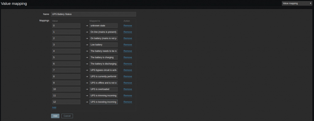
On your desktop, download/clone the git repository. Log into Zabbix. Follow the instructions and create the value mapping.

Import the Zabbix template. In the usual way and link it to your servers.

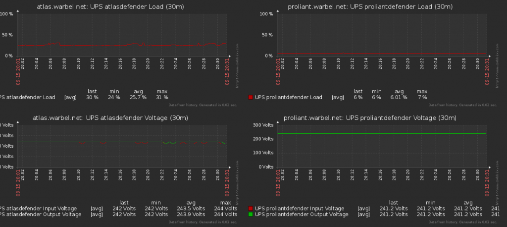
If you feel like it, create a new screen to monitor your UPS.

And you’re done! No more guessing and hoping your UPS’s haven’t swapped to battery when you’re away from home.

Troubleshooting:


The Powershield UPS that uses the driver usbhid-ups has a habit of dropping out, with the error message that the data is stale. I attempted  a work around with a script with the following in /root/restart_service.sh:

#!/bin/sh
#Get the error state:
ErrorState=`upsc defender@localhost 2>&1|grep -v SSL|cut -b 1-5|tail -1`;
#If the error state is equal to "Error" then restart the service
if [ $ErrorState = "Error" ]
then
 service nut-server restart
 echo "Restarting nut-server" >> /var/log/syslog
fi

And edited the crontab for root with sudo crontab -e and add the following line:

* * * * * /bin/bash -l -c "/root/restart_service.sh; sleep 30 ; /root/restart_service.sh"

Unfortunately this did not resolve my issue! Eventually I played around with a few settings, ultimately arriving at adjusting the maxretry in ups.conf. Changing it to:

maxretry=5

I also adjusted the polling interval to 60 seconds.

Resources:

Big thanks to http://nitestick.net/nut-for-defender-1200/ whom I mostly followed to get this working.
Blazer USB documentation: http://networkupstools.org/docs/man/blazer_usb.html
Zabbix NUT templates: https://github.com/delin/Zabbix-NUT-Template
NUT documentation page, which helped me to narrow down the drivers I needed: http://networkupstools.org/stable-hcl.html
I also referenced: http://tedfelix.com/software/nut-network-ups-tools.html

Useful Zabbix Templates

I’ve recently turned my attention to improving my monitoring solution: Zabbix. Zabbix has the ability to probe much more than just network information through the use of scripts and templates. I’ve recently installed three such templates:

The installation instructions for each were straightforward. Only Speedtest needed additional tweaking to work, specifically, speedtest-cli needed to be installed.

How to Configure Collabora with NextCloud behind an Apache2 Reverse Proxy

Background:

I’ve become increasingly aware (read: paranoid) about the amount of information that Google and Facebook collect about me which they then sell to advertisers for a profit. I don’t appreciate Google reading my emails and personal communications and using that information to sell advertising. Unfortunately for me their services are useful but are replaceable, at leas for me with a fast NBN connection. As such I’ve set off to remove my self as much as possible from their reach.

I’ve already setup mailinabox and Nextcloud, but I’ve missed the ability to edit documents online with Google Drive. Thankfully Nextcloud provide an answer with Collabora. Unfortunately their documentation isn’t very clear, however with a little playing around I was able to get things working. 🙂

Process:

On my web server virtual machine, I installed docker and docker.io

sudo apt install docker docker.io

Download collabora:

sudo docker pull collabora/code

As per the instructions, create a new subdomain (with letsencrypt) called office.warbel.net. If you use letsencrypt, you will need to create a new certificate inclusive of all your domains hosted on the web server.

sudo service apache2 stop
sudo letsencrypt certonly -d bel.warbel.net -d www.warbel.net -d blog.warbel.net -d travel.warbel.net -d mattermost.warbel.net -d office.warbel.net
sudo service apache2 start

Run the Collabora image. Being sure to run the image with the domain name of the server that hosts the image, NOT office.yourdomain.net

sudo docker run -t -d -p 127.0.0.1:9980:9980 -e 'domain=www\\.warbel\\.net' --restart always --cap-add MKNOD collabora/code

Run the command to check the status of the image:

sudo docker ps

Will return: (the name will change, it is random)

CONTAINER ID IMAGE COMMAND CREATED STATUS PORTS NAMES
2e21004691d9 collabora/code "/bin/sh -c 'bash sta" 3 days ago Up 3 days 127.0.0.1:9980->9980/tcp boring_ardinghelli

To stop, and then kill the docker image:

sudo docker stop boring_ardinghelli; sudo docker rm boring_ardinghelli

Once you are confident that the image is up and running create a new site in /etc/apache2/sites-available/ and call it what you will. I called mine: office.warbel.net.conf with the following configuration:

<VirtualHost office.warbel.net:443>

ServerName office.warbel.net
SSLHonorCipherOrder on

# Encoded slashes need to be allowed
AllowEncodedSlashes NoDecode

# Container uses a unique non-signed certificate
SSLProxyEngine On
SSLProxyVerify None
SSLProxyCheckPeerCN Off
SSLProxyCheckPeerName Off

# keep the host
ProxyPreserveHost On

# static html, js, images, etc. served from loolwsd
# loleaflet is the client part of LibreOffice Online
ProxyPass /loleaflet https://127.0.0.1:9980/loleaflet retry=0
ProxyPassReverse /loleaflet https://127.0.0.1:9980/loleaflet

# WOPI discovery URL
ProxyPass /hosting/discovery https://127.0.0.1:9980/hosting/discovery retry=0
ProxyPassReverse /hosting/discovery https://127.0.0.1:9980/hosting/discovery

# Main websocket
ProxyPassMatch "/lool/(.*)/ws$" wss://127.0.0.1:9980/lool/$1/ws nocanon

# Admin Console websocket
ProxyPass /lool/adminws wss://127.0.0.1:9980/lool/adminws

# Download as, Fullscreen presentation and Image upload operations
ProxyPass /lool https://127.0.0.1:9980/lool
ProxyPassReverse /lool https://127.0.0.1:9980/lool

</VirtualHost>

Finally, in nextcloud, add the plugin as per nextclouds documentation and add the domain office.yourdomain.com:443 to the collabora plugin url.

Troubleshooting:

I have a unique custom firewall script that interferes with docker.io. Docker, when it creates a container will add rules to it’s own chain. However my firewall script will delete those chains when it starts. The work around is to restart the docker.io service after the machine boots to recreate the chain and allow networking to start.

I’ve also had to add custom firewall chains to my scripts to allow docker to work.These are (iptables -S):

-A FORWARD -j DOCKER-ISOLATION
-A FORWARD -o docker0 -j DOCKER
-A FORWARD -o docker0 -m conntrack --ctstate RELATED,ESTABLISHED -j ACCEPT
-A FORWARD -i docker0 ! -o docker0 -j ACCEPT
-A FORWARD -i docker0 -o docker0 -j ACCEPT
-A DOCKER -d 172.17.0.2/32 ! -i docker0 -o docker0 -p tcp -m tcp --dport 9980 -j ACCEPT
-A DOCKER-ISOLATION -j RETURN

When the machine restarts I need to manually restart docker to get things going again. I’ll figure out how to fix this later…

Docker taking up too much space.

I’ve found that every time I’ve killed and started the docker image the space the image takes up remains. Some googling has helped me find a solution:

docker rmi $(docker images -f "dangling=true" -q)

and

docker rm -v $(docker ps -a -q -f status=exited)

Do the job pretty well.

Configuring a Raspberry Pi 2 with a Huwei K4203 USB 3G Modem

Background/Overview:

My Wife and I like to travel overseas and we both have multiple devices when we travel. Over the years we’ve tried different solutions. From buying ‘travel’ sims before we leave that end up costing a fortune, to just enabling roaming on our phones and again, paying heavily for international data roaming.

After doing a little research on the best deal and wanting a flexible option, I bought a 3G dongle from Vodafone. A Huawei K4204 to be precise. My goal is to create a Raspberry Pi that will connect to the hotel WiFi when available and will have it’s own AP running on a different channel so that our devices only have to remember one Access Point.  This will circumvent certain hotels that only allow you to connect a single device to their network. It will also mean that if we have a Google Chromecast I only have to program a single network into it and use it when we travel. The Raspberry Pi will have a 3G data connection when no Hotel WiFi is available or we’re out and about. When we arrive at our destination (the UK) we will buy a local sim with local (read: cheap) data.

The below steps are how I achieved the above:

Part 1: Initial Setup

Install Raspbian in any way you prefer. I’ve installed the lite version that has no gui.

Use dd to write to the disk, in my case the microSD card was at /dev/sdd:

sudo dd if=2017-04-10-raspbian-jessie-lite.img of=/dev/sdd bs=2M

log in as pi, password: raspberry

add a new user and add the user to the sudo group so you can edit system files:

sudo adduser wargus;sudo usermod -a -G sudo USERNAME

log in as your new user, remove pi

sudo deluser pi

enable ssh by default using raspi-config

sudo raspi-config

Under Interfacing Options, 2, Enable SSH:

Check the IP address of the raspberry pi, it should be set to dhcp automatically.

ifconfig 
eth0 Link encap:Ethernet HWaddr 00:00:00:00:00:00 
 inet addr:10.60.204.182 Bcast:10.60.204.255 Mask:255.255.255.128
 UP BROADCAST RUNNING MULTICAST MTU:1500 Metric:1
 RX packets:7511 errors:0 dropped:12 overruns:0 frame:0
 TX packets:2759 errors:0 dropped:0 overruns:0 carrier:0
 collisions:0 txqueuelen:1000 
 RX bytes:669438 (653.7 KiB) TX bytes:604742 (590.5 KiB)

At this point you can disconnect the terminal and use SSH to connect to your raspberry device.

Configuring usb_modeswitch

I used this site as a reference. It was mostly right for me, although I did have to do a lot troubleshooting before I had it completely right.

cd /tmp
tar -xzvf /usr/share/usb_modeswitch/configPack.tar.gz 19d2\:1f1c

Will create a new file in the tmp directory it will need to be further edited to look like this:

# Vodafone / Huawei K4203
DefaultVendor=0x12d1
DefaultProduct=0x1f1c
TargetVendor=0x12d1
TargetProductList="157a,1590"
HuaweiNewMode=1

Copy or move that file to /etc/usb_modeswitch.d/

At this point with a fresh install, you should be able to plug in the dongle. Switch the usb mode by running :

sudo usb_modeswitch -c /etc/usb_modeswitch.d/12d1\:1f1c

Check the switch by using lsusb, as the output suggests.

lsusb
Bus 001 Device 007: ID 12d1:1590 Huawei Technologies Co., Ltd. 
Bus 001 Device 004: ID 0bda:8178 Realtek Semiconductor Corp. RTL8192CU 802.11n WLAN Adapter
Bus 001 Device 003: ID 0424:ec00 Standard Microsystems Corp. SMSC9512/9514 Fast Ethernet Adapter
Bus 001 Device 002: ID 0424:9514 Standard Microsystems Corp. 
Bus 001 Device 001: ID 1d6b:0002 Linux Foundation 2.0 root hub

In my setup, the dongle flashed green, flashed blue, then goes solid blue. A quick check of ifconfig at this point shows that the dongle presents itself as a new Ethernet adaptor:

ifconfig 
...
eth1 Link encap:Ethernet HWaddr 00:00:00:00:00:00 
inet addr:192.168.9.100 Bcast:192.168.9.255 Mask:255.255.255.0
UP BROADCAST RUNNING MULTICAST MTU:1500 Metric:1
RX packets:55 errors:0 dropped:0 overruns:0 frame:0
TX packets:38 errors:0 dropped:0 overruns:0 carrier:0
collisions:0 txqueuelen:1000 
RX bytes:16310 (15.9 KiB) TX bytes:7400 (7.2 KiB)

The dongle automagically configures itself and connects to the internet. 🙂 Remember that at this point to connect to the internet will require you to manually set the dongle to the correct mode.

Test the connection by pinging over the interface:

ping www.google.com -I eth1
PING www.google.com (203.219.197.210) from 192.168.9.100 eth1: 56(84) bytes of data.
64 bytes from cache.google.com (203.219.197.210): icmp_seq=1 ttl=55 time=2254 ms
64 bytes from cache.google.com (203.219.197.210): icmp_seq=2 ttl=55 time=1248 ms
64 bytes from cache.google.com (203.219.197.210): icmp_seq=3 ttl=55 time=248 ms

ping www.google.com -I eth0
PING www.google.com (203.219.197.245) from 10.60.204.182 eth0: 56(84) bytes of data.
64 bytes from cache.google.com (203.219.197.245): icmp_seq=1 ttl=60 time=1.85 ms
64 bytes from cache.google.com (203.219.197.245): icmp_seq=2 ttl=60 time=1.50 ms
64 bytes from cache.google.com (203.219.197.245): icmp_seq=3 ttl=60 time=2.33 ms

Part 2: Routing Configuration

At this point, we have a very smart little independently internet connected Raspberry Pi. What we want to do next is a little more complicated. We’re going to configure it to be an access point that will hand out IP addresses and handle NAT. unfortunately it won’t be smart enough to switch between wifi and 3G automatically however you can connect and do that yourself. 😉

Linux by default does not know that it is a router. We need to enable that functionality and, while we’re there, disable IPv6 (which is something of a security concern).

Edit /etc/sysctl.conf with your favourite editor and uncomment the line:

net.ipv4.ip_forward=1

Add the following lines:

net.ipv6.conf.all.disable_ipv6=1
net.ipv6.conf.default.disable_ipv6=1

Then run the following command to make the changes apply:

sudo sysctl -p

Install hostapd and configure your wifi dongle to be an access point:

sudo apt-get install hostapd -y

Edit the primary wifi dongle to be an access point by editing /etc/hostapd.conf

channel=3
country_code=AU
hw_mode=g
interface=wlan0
ssid=SSIDNAME
wpa=2
wpa_key_mgmt= WPA-PSK WPA-EAP WPA-PSK-SHA256 WPA-EAP-SHA256
wpa_passphrase=PASSPHRASE

You will need to edit the above to suit. Be sure to check what channels are being used and pick one that does not have too much interference.

Now edit the /etc/network/interfaces file and change wlan0’s settings:

auto wlan0
allow-hotplug wlan0
iface wlan0 inet static
hostapd /etc/hostapd/hostapd.conf
address 10.60.205.129
netmask 255.255.255.128
broadcast 10.60.205.255
dns-nameservers 8.8.8.8 8.8.4.4

To save heartache later, edit the default settings for eth0 to:

iface eth0 inet dhcp

To explain the above: I’ve gone with a small 10.60.205.128/25 IP range and I’ve set google’s name servers to be my defaults. It is necessary to change eth0’s settings as it will fail to come up when we change some service settings below.

Finally, setup a dhcp server. I tend to prefer a more robust dhcp server:

sudo apt-get install isc-dhcp-server

Configure it to only operate on the wlan0 interface by editing /etc/default/isc-dhcp-server and changing the line INTERFACES=”” to

INTERFACES="wlan0"

Edit the configuration file for the dhcp server in /etc/dhcp/dhcpd.conf Change various options at the top to match your own configuration, the important points to recognise are:

# option definitions common to all supported networks...
option domain-name "yourdomain.local";
option domain-name-servers 8.8.8.8, 8.8.4.4;

subnet 10.60.205.128 netmask 255.255.255.128 {
range 10.60.205.150 10.60.205.190;
option routers 10.60.205.129;
option broadcast-address 10.60.205.255;
}

This will create a range of IP addresses to assign to devices as needed from 150 to 190.  We still won’t have routing yet, but we’re nearly there! Enable the dhcp service:

sudo systemctl enable isc-dhcp-server.service

Start the dhcp server:

sudo service isc-dhcp-server start

It should be safe to start the service now, and test  everything be restarting it. if you connect a device to the network it will be able to get an IP address, it just won’t have any internet access.

If you have another wifi dongle, as I do, it can also be configured to be a client to another wireless network. This is handy if your hotel only allows one device to be connected to their wifi and you have many devices. Connect the Raspberry Pi to their network and have it do NAT to your devices.

The Configuration at home may be different to the hotel, which is why I’ve included the note in the configuration below to remind me where to look for information. Remember, if you need to find more information you can always use the 3G dongle to get access to the internet 🙂

#Configure the roaming interface
#Use 'sudo iwlist scan' to find an AP to join
auto wlan1
allow-hotplug wlan1
iface wlan1 inet dhcp
wpa-ssid SSID_OF_NETWORK
wpa-psk PASSWORD

The Final Steps: Routing and Firewalling.

At this point we can write a simple script called firewall to allow routing. It can be placed in /etc/init.d/.

#!/bin/bash

# Iptables Location
IPTABLES="/sbin/iptables"
#Load Modules#

##########################################################
#
# Don't Touch anything below this line!
#

case "$1" in start)

echo "Starting Firewall Services"
echo "Firewall: Configuring firewall rules using iptables"

#BEGIN FIREWALL ROUTING HERE

#We want the 3G router to start when the firewall does. So we use usb switch here:
usb_modeswitch -c /etc/usb_modeswitch.d/12d1\:1f1c

#Flush Routing Table
$IPTABLES -F
$IPTABLES -t nat -F
$IPTABLES -t mangle -F
$IPTABLES -t mangle -X
$IPTABLES -X

# default policy
 $IPTABLES -P INPUT ACCEPT
 $IPTABLES -P FORWARD ACCEPT
 $IPTABLES -P OUTPUT ACCEPT

# allow established,related
 $IPTABLES -A INPUT -m state --state ESTABLISHED,RELATED -j ACCEPT
 $IPTABLES -A FORWARD -m state --state ESTABLISHED,RELATED -j ACCEPT

# Masquerade over both routes
 $IPTABLES -t nat -A POSTROUTING -o eth1 -j MASQUERADE
 $IPTABLES -t nat -A POSTROUTING -o wlan1 -j MASQUERADE
#END FIREWALL ROUTING HERE

touch /var/lock/firewall
;;
status)
 if [ -f /var/lock/firewall ]; then
 echo "Firewall started and configured"
 else
 echo "Firewall stopped"
 fi
 exit 0
 ;;

restart|reload)
 $0 stop
 $0 start
 ;;

stop)
 echo "Shutting down Firewall services"

#Flush Routing Table
$IPTABLES -F
$IPTABLES -t nat -F
$IPTABLES -t mangle -F
$IPTABLES -t mangle -X
$IPTABLES -X

# default policy
 $IPTABLES -P INPUT ACCEPT
 $IPTABLES -P FORWARD ACCEPT
 $IPTABLES -P OUTPUT ACCEPT

 rm -f /var/lock/firewall
 echo
 ;;
 *)
 echo "Usage: /etc/init.d/firewall {start|stop|status|restart|reload}"
 exit 1
esac
exit 0

I’ve noticed that by default the router will route traffic over the wlan1 before eth1, even if eth1 exists and has internet access. This is useful as it means that we can have a single firewall/routing script for both connections. It will fail-over to the 3G dongle when no appropriate WiFi AP can be found.

Install the script with:

sudo update-rc.d firewall defaults

At this point I was able to power down the Raspberry Pi. On coming back online the two dongles didn’t work, but the 3G dongle did. As hotplug is enabled on those two wifi dongles, removing and re-inserting them got them working again. I was then able to connect to the internet (and the Pi) over WiFi. Removing the dongle connecting to my home network immediately failed over to the 3G dongle.

Which brings us to the end!


Monitoring Plex with Plexpy on Ubuntu 16.04

Background:

Plex, for a multi-user multi-media system, lacks detailed logging and monitoring. A colleague recently pointed out to me that another system, PlexPY exists to fill that gap. This blog post will walk through the steps I took to integrate the system into my reverse proxy and setup init scripts.
Plexpy itself, has quite good documentation here (for initial setup) and here (for creating system init scripts).

Creating a new service:

This is straightforward, and can be done by following the documentation above. No changes were necessary to have it running on Ubuntu 16.04.

  1. Create the user to run the service:
    sudo adduser --system --no-create-home plexpy
  2. Change the ownership of the file structure to allow the new user to modify the files:
    sudo chown plexpy:nogroup -R /opt/plexpy
  3. Create the init script:
    sudo vi /lib/systemd/system/plexpy.service
  4. Put the following in the file:
    [Unit]
    Description=PlexPy - Stats for Plex Media Server usage
    
    [Service]
    ExecStart=/opt/plexpy/PlexPy.py --quiet --daemon --nolaunch --config /opt/plexpy/config.ini --datadir /opt/plexpy
    GuessMainPID=no
    Type=forking
    User=plexpy
    Group=nogroup
    
    [Install]
    WantedBy=multi-user.target
  5. Reload the services, enable plexpy and start it:
    sudo systemctl daemon-reload; sudo systemctl enable plexpy.service; sudo service plexpy start

Configuring Apache reverse proxy to allow access:

  1. Shutdown Apache and PlexPY:
    sudo service plexpy stop
    sudo service apache2 stop
  2. Change the settings in PlexPY to make it work behind a reverse proxy. Edit the config file and change the lines to:
    http_root = /plexpy
    http_proxy = 1
  3. Edit your Apache reverse config file for the domain hosting plexpy:
    ProxyPass /plexpy http://Local_IP_of_plexpy:8181/plexpy/
    ProxyPassReverse /plexpy http://Local_IP_of_plexpy:8181/plexpy/
  4. Start the services again:
    sudo service plexpy start
    sudo service apache2 start
  5. Test: